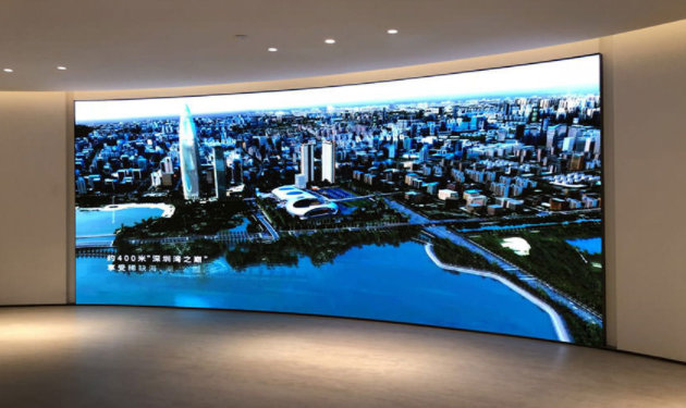
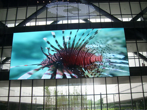
The production of small-pitch LED displays involves those technical processes
1.Packaging technology
Small-pitch LED displays with a density below P2 generally use 0606, 1010, 1515, 2020, 3528 lamps, and the shape of the LED pins is J or L package. If the pins are welded sideways, there will be reflections in the welding area, and the ink color effect will be poor. It is necessary to add a mask to improve the contrast. If the density is further increased, the L or J package cannot meet the application requirements, and the QFN package must be used. The characteristic of this process is that there are no laterally welded pins, and the welding area is non-reflective, which makes the color rendering effect very good. In addition, the all-black integrated design is molded by molding, and the contrast of the screen is increased by 50%, and the image quality of the display application is better than that of the previous display.
2.Mounting technology:
The slight offset of the position of each RGB device in the micro-pitch display will result in uneven display on the screen, which is bound to require the placement equipment to have higher precision.
3. Welding process:
If the reflow soldering temperature rises too fast, it will lead to unbalanced wetting, which will inevitably cause the device to shift during the process of unbalanced wetting. Excessive wind circulation can also cause displacement of the device. Try to choose a reflow soldering machine with more than 12 temperature zones, chain speed, temperature rise, circulating wind, etc. as strict control items, that is, to meet the requirements of welding reliability, but also to reduce or avoid the displacement of components, and try to control it within the scope of demand. Generally, 2% of the pixel pitch is used as the control value.

4. Printed circuit board process:
With the development trend of micro-pitch display screens, 4-layer and 6-layer boards are used, and the printed circuit board will adopt the design of fine vias and buried holes. The mechanical drilling technology can no longer meet the requirements, and the rapidly developed laser drilling technology will meet the micro hole processing.
5. Printing technology:
The correct PCB pad design needs to be communicated with the manufacturer and implemented into the design. Whether the opening size of the stencil and the correct printing parameters are directly related to the amount of solder paste printed. Generally, 2020RGB devices use electro-polished laser stencils with a thickness of 0.1-0.12mm, and 1.0-0.8 thickness stencils are recommended for devices below 1010RGB. Thickness and opening size increase in proportion to the amount of tin. The quality of micro-pitch LED soldering is closely related to solder paste printing. The use of functional printers with thickness detection and SPC analysis will play an important role in reliability.
6. Screen assembly:
The assembled box needs to be assembled into a screen before it can display refined pictures and videos. However, the dimensional tolerance of the box itself and the cumulative tolerance of the assembly cannot be ignored for the assembly effect of the micro-pitch display. If the pixel pitch of the nearest device between the cabinet and the cabinet is too large or too small, dark lines and bright lines will be displayed. The problem of dark lines and bright lines is a problem that cannot be ignored and needs to be solved urgently for micro-pitch display screens such as P1.25. Some companies make adjustments by sticking 3m tape and finely adjusting the nut of the box to achieve the best effect.
7. Box assembly:
The cabinet is made of different modules spliced together. The flatness of the cabinet and the gap between the modules are directly related to the overall effect of the cabinet after assembly. Aluminum plate processing box and cast aluminum box are the most widely used box types at present. The flatness can reach within 10 wires. The splicing gap between modules is evaluated by the distance between the nearest pixels of the two modules. lines, two pixels too far will result in dark lines. Before assembling, it is necessary to measure and calculate the joint of the module, and then select a metal sheet of relative thickness as a fixture to be inserted in advance for assembly.
Post time: May-13-2022

